Power Attenuator
No guitarist should be without one. For those of you who are unfamiliar with the concept, an attenuator converts the output of your tube amp into heat, thus allowing you to crank your amp without the ear crushing volume.
My design uses a 100 watt L-Pad to attenuator the power of the amp. Because heavy attenuation can cause tone loss, I have included a bright switch to help compensate for the loss in treble. Also, I included a bypass switch for obvious reasons. This design is a combination of two DIY pages- This site is the basis for my attenuator: http://www.guitarpug.com/2008/07/diy-wattage-attenuator-box/ I also included the bright/bypass switch from this page: http://www.regiscoyne.com/ampwell/ All of these parts can be purchased at your local Radio Shack with the exception of the L-Pad. I bought mine from Parts Express for $12 plus shipping. The total cost of this attenuator was less than $40. | 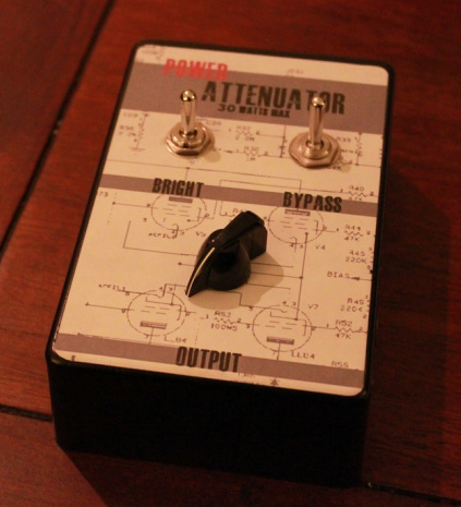 |
Preparing My Amplifier
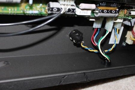
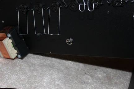
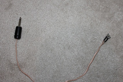
I built this attenuator for my Peavey Classic 30 combo. If you have a head/cab set-up all you do not need to alter your amp. If you're using the attenuator with a combo, you need to have some way to connect the amp output to the attenuator and the attenuator to your speaker. I simply disconnected the speaker wire, drilled a 3/8" hole in the bottom of my amp chassis, and wired the output to a 1/4" jack. Then I fashioned a new speaker cable to connect the output jack to the speaker. This way I can easily connect and disconnect my attenuator.
 |  |
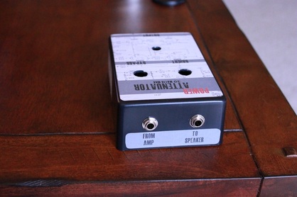
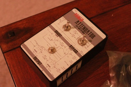
Attenuator Case
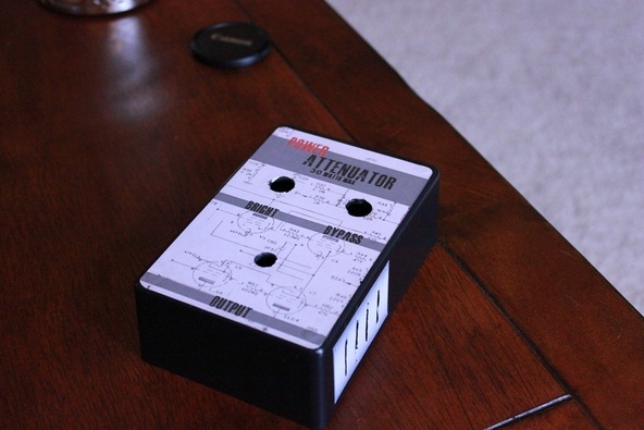
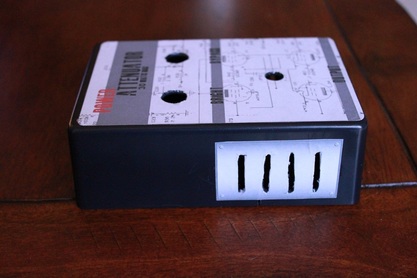
For the case itself I purchased a 6x4x2 project box from Radio Shack. The nice thing about these is that they are durable, but they are easy to cut/drill. I determined a simple layout based on the size of the components and ease of use. The input/output jacks are on the back, the level knob closest to me and the switches above that. Next I designed a faceplate to cover the front of the project enclosure using Microsoft Word. I downloaded an open source font from dafont.com and used it to create the labels for the controls. Also, the background schematic is actually the power section of a Peavey Classic 30 (which I thought was a nice touch). I printed the front panel, back panel, and side decals with a regular inkjet printer onto some sticker paper. You can buy the paper at office supply stores or walmart. The paper I used is for shipping labels, but it works perfectly for my purposes as well. Finally, I drilled the holes for my controls and jacks, and then cut some vents in the sides to help reduce the heat of the L-Pad.
 |  |
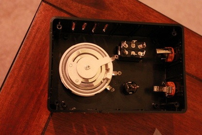
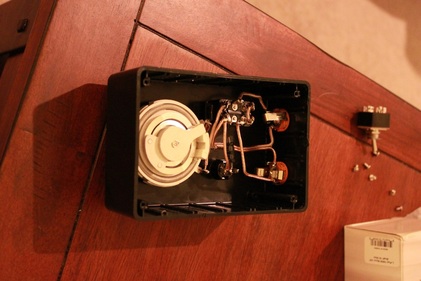
Wiring the components
I removed the back cover from my L-Pad to help dissipate the heat, and the I installed all of the components into the case. After that it was simply a matter of soldering everything together. Because the L-Pad can get exceptionally hot, it is a good idea to make a strong physical connection with the wire before soldering them into place. I inserted the wire through the holes in the soldering tabs and then twisted them back around. This way if the solder is compromised due to heat I will still have a connection.
I used the following components:
Bypass switch- DPDT
Bright Switch - SPDT (SPST OR DPDT will also work)
1/4" Jacks (any kind will work)
L-Pad - 16ohm 100 watts
Capacitor- 4.7 uf non-polarized electrolyte capacitor (available at radioshack)
I used the following components:
Bypass switch- DPDT
Bright Switch - SPDT (SPST OR DPDT will also work)
1/4" Jacks (any kind will work)
L-Pad - 16ohm 100 watts
Capacitor- 4.7 uf non-polarized electrolyte capacitor (available at radioshack)
 |  |
Here is a youtube video of the attenuator in action. The video itself doesn't really do it justice, but it gives you an idea of the attenuator's ability to effectively control volume and also the utility of the bright switch.
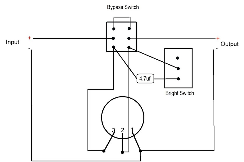
Also, I've posted a wiring diagram complete with bypass and bright switches. |